
サマリ
- Segment Routing Traffic Engineering(SR-TE)を一元管理可能な経路計算サーバである Path Computation Element(PCE)を紹介
- SR-PCE を用いて PE へ SR Policy を送信し、SR-TE の一元管理を検証
この記事は Multi-AS Segment Routing 検証連載の第 10 回です。目次は こちら
概要
イノベーションセンターの三島です。 本記事では SR-TE を効率的に管理・運用するための実現手法である PCE を紹介し、PCE を用いた SR Policy の管理を検証します。
SR-TE の問題点と Path Computation Element(PCE)
SR-TE は様々な要件を実現するために使われます。 例えば、複数の利用者・複数のアプリケーションごとの目的に応じた Quality of Service(QoS)要件、 Service Function Chaining(SFC)要件、リンク利用率の要件などです。 これらの要件の中には帯域保証やリンク利用率の最適化など、ネットワーク全体の状態を把握したときにのみ真に最適なパスを計算できるものが存在します。 そのような複雑な要件を満たす SR Policy を各 PE ルーターで分散して計算するには限界があります。
一方で、SR-TE の実装には各 PE ルーターへの設定が必要です。 台数が増えるに従って設定作業のみならず、パスに用いる SID をはじめとしたパラメータの管理も複雑になります。
そこでコントローラーを用いて SR-TE を一元管理することにより、ネットワーク全体の状態を把握したうえでパスを計算し、かつ、設定項目を集約できることが期待されます。 このような SR-TE の一元管理を実現する技術として Path Computation Element(PCE)があります。
PCE は、歴史的には MPLS 網の TE を一元管理するために考案された技術であり、 RFC5440/8231/8281/8664 などで標準化されています。 一般的な PCE の構成を下記に示します。
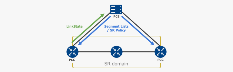
PCE から SR-TE の経路を受け取るノードを Path Computation Client(PCC)と呼びます。 PCC は、PCE から Segment List や Policy 名、Color など、ある宛先に対する SR Policy を構成するための情報を受信し、SR-TE を実現します。
PCE と PCC の間は、SR ネットワークの LinkState の共有(図中緑部分の通信)と、作成した経路の共有(図中水色部分の通信)が行われます。 PCEP や BGP SR Policy は経路を state として、NETCONF は経路を config としてそれぞれ扱うことができます。
LinkState の共有
LinkState の共有には、BGP-LS という技術が用いられます。 BGP-LS とは、Multi-Protocol BGP(MP-BGP)を利用した LinkState の共有技術であり、RFC7752 で標準化されています。 MP-BGP の Address Family Identifier(AFI)16388、Sub-AFI(SAFI)71 を利用し、IS-IS や OSPF の LinkState を送信します。
PCE は BGP-LS により SR ネットワークの LinkState を収集することで、SR domain の トポロジーと SID 情報を入手し経路計算を実現します。
経路情報の共有
経路情報の共有には、BGP SR Policy、NETCONF の他に、Computation Element Communication Protocol(PCEP)という技術が用いられます。 PCEP とは、PCE-PCC 間や複数の PCE 間の通信を実現するプロトコルです。 TCP port 4189 を利用し、Segment List や SR Policy 名、Affinity など様々な情報を送受信できます。
なお、本記事では PCEP を利用して検証を実施します。
Stateless PCE と Stateful PCE
PCE には、発行済み の 経路(LSP / SR Policy)や帯域などの予約済みリソース、パス計算要求などの情報を管理しない Stateless PCE と、これらの情報を管理する Stateful PCE が存在します。 Stateful PCE は既存の予約済みリソースを管理するため、それらを条件として考慮した複雑な経路を計算することが可能となります。
Stateful PCE には、PCC からのリクエストに基づいた経路計算のみを行う Passive Stateful PCE と、自ら経路を発行し PCC へ送信する Active Stateful PCE が存在します。 Active Stateful PCE は新規 SR Policy の発行や既存 SR Policy の更新などの操作を実現できるため、SR Policy の集中的な管理に適しています。
次章では、Active Stateful PCE による SR Policy の集中的な管理を目的とし動作検証を行います。
検証
本章では、IOS XR に実装された SR-PCE 機能を利用し、Cisco/Juniper それぞれの PCC に SR Policy を送信します。 検証に使用するトポロジーは下記の通りです。
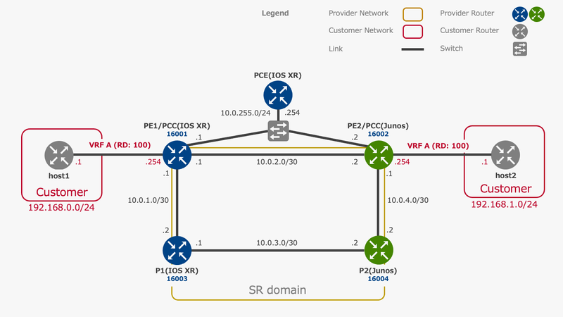
このトポロジーにおいて PCE から PE1/PE2 のそれぞれに SR Policy を送信し、下記の経路を実現します。

以降では、下記の手順で PCE による SR-TE の一元管理を検証します。
- BGP-LS ・ PCEP の設定: PCE ・ PCC のそれぞれに BGP-LS ・ PCEP を設定し、Active Stateful PCE による SR-TE の一元管理環境を構成
- SR Policy の設定: PCE に対し、送信する SR Policy を設定
- 動作確認: BGP-LS ・ PCEP セッション・ SR Policy の状態確認と Traceroute による動作確認
1. BGP-LS ・ PCEP の設定
PCE
BGP-LS
PE1 ・ PE2 向けの BGP-LS 設定を投入します。
※ 最低限1つのピアを設定すれば BGP-LS ですべての情報を受信し動作可能です。本検証では冗長化と Multi-vendor の相互接続検証を兼ねるため、双方に向けて設定します。
router bgp 65000
 bgp router-id 10.255.0.254
 address-family link-state link-state
 !
 neighbor 10.0.255.1
  remote-as 65000
  address-family link-state link-state
  !
 !
 neighbor 10.0.255.2
  remote-as 65000
  address-family link-state link-state
  !
 !
!
PCEP
PCEP の待ち受けアドレスを指定します。
※ IOS XR の SR-PCE 機能の仕様上、PCC 側が PCEP セッションに利用するアドレスは、BGP-LS の LinkState から参照可能な必要があるようです。そのため本検証環境では Loopback アドレスを PCEP セッションに利用します。
pce
 address ipv4 10.0.255.254
PCC/PE1(IOS XR)
BGP-LS IS-IS を TED に export し、BGP-LS で PCE へ広告します。
router isis 1
 distribute link-state instance-id 32
!
router bgp 65000
 address-family link-state link-state
 !
 neighbor 10.255.0.254
  remote-as 65000
  update-source Loopback0
  address-family link-state link-state
  !
 !
!
PCEP
PCC 機能を設定し、PCEP を利用可能にします。
segment-routing
 traffic-eng
  pcc
   source-address ipv4 10.255.0.1
   pce address ipv4 10.255.0.254
PCC/ PE2(Junos)
BGP-LS
IS-IS を TED に export し、BGP-LS で PCE へ広告します。
set policy-options policy-statement TE term 1 from family traffic-engineering
set policy-options policy-statement TE term 1 then accept

set protocols mpls traffic-engineering database import policy TE

set routing-options autonomous-system 65000
set protocols bgp group SR-PCE type internal
set protocols bgp group SR-PCE local-address 10.255.0.2
set protocols bgp group SR-PCE family traffic-engineering unicast
set protocols bgp group SR-PCE export TE
set protocols bgp group SR-PCE neighbor 10.255.0.254
PCEP
PCC 機能を設定し、PCEP を利用可能にします。
set protocols mpls lsp-external-controller pccd
set protocols source-packet-routing lsp-external-controller pccd
set protocols pcep pce SR-PCE local-address 10.255.0.2
set protocols pcep pce SR-PCE destination-ipv4-address 10.255.0.254
set protocols pcep pce SR-PCE pce-type active
set protocols pcep pce SR-PCE pce-type stateful
set protocols pcep pce SR-PCE lsp-provisioning
set protocols pcep pce SR-PCE spring-capability
2. SR Policy の設定(PCE)
PE1 から PE2、 PE2 から PE1 への各 SR-TE 経路を記述した SR Policy を設定します。
pce
 segment-routing
  traffic-eng
   segment-list name PE1-to-PE2
    index 1 mpls label 16003
    index 2 mpls label 16004
    index 3 mpls label 16002
   !
   segment-list name PE2-to-PE1
    index 1 mpls label 16004
    index 2 mpls label 16003
    index 3 mpls label 16001
   !
   peer ipv4 10.255.0.1
    policy PE1
     candidate-paths
      preference 1
       explicit segment-list PE1-to-PE2
       !
      !
     !
    !
   !
   peer ipv4 10.255.0.2
    policy PE2
     candidate-paths
      preference 1
       explicit segment-list PE2-to-PE1
       !
      !
     !
    !
   !
  !
 !
!
3. 動作確認
PCE
BGP-LS
BGP-LS による LinkState 受信を確認します。(出力が長いため一部省略)
RP/0/RP0/CPU0:pce#show bgp link-state link-state
Thu Oct 13 17:10:53.338 JST
BGP router identifier 10.255.0.254, local AS number 65000
BGP generic scan interval 60 secs
Non-stop routing is enabled
BGP table state: Active
Table ID: 0x0   RD version: 339
BGP main routing table version 339
BGP NSR Initial initsync version 13 (Reached)
BGP NSR/ISSU Sync-Group versions 0/0
BGP scan interval 60 secs

Status codes: s suppressed, d damped, h history, * valid, > best
              i - internal, r RIB-failure, S stale, N Nexthop-discard
Origin codes: i - IGP, e - EGP, ? - incomplete
Prefix codes: E link, V node, T IP reacheable route, S SRv6 SID, u/U unknown
              I Identifier, N local node, R remote node, L link, P prefix, S SID
              L1/L2 ISIS level-1/level-2, O OSPF, D direct, S static/peer-node
              a area-ID, l link-ID, t topology-ID, s ISO-ID,
              c confed-ID/ASN, b bgp-identifier, r router-ID, s SID
              i if-address, n nbr-address, o OSPF Route-type, p IP-prefix
              d designated router address
   Network            Next Hop            Metric LocPrf Weight Path
*>i[V][L2][I0x0][N[c65000][s0000.0aff.0001.00]]/264
                      10.255.0.2                    100      0 i
*>i[V][L2][I0x0][N[c65000][s0000.0aff.0002.00]]/264
                      10.255.0.2                    100      0 i
*>i[V][L2][I0x0][N[c65000][s0000.0aff.0003.00]]/264
                      10.255.0.2                    100      0 i
*>i[V][L2][I0x0][N[c65000][s0000.0aff.0004.00]]/264

<略>
PCEP
PCC とのセッションを確認します。
detail オプションを 利用することで PCEP で送受信されたメッセージの詳細を確認できます。
RP/0/RP0/CPU0:pce#show pce ipv4 peer detail
Thu Oct 13 16:55:22.855 JST

PCE's peer database:
--------------------
Peer address: 10.255.0.1
  State: Up
  Capabilities: Stateful, Segment-Routing, Update, Instantiation
  PCEP has been up for: 00:02:04
  PCEP session ID: local 0, remote 0
  Sending KA every 30 seconds
  Minimum acceptable KA interval: 20 seconds
  Peer timeout after 120 seconds
  Maximum SID Depth: 10
  Statistics:
    Keepalive messages: rx 4 tx 5
    Request messages:   rx     0 tx     0
    Reply messages:     rx     0 tx     0
    Error messages:     rx     0 tx     0
    Open messages:      rx     1 tx     1
    Report messages:    rx     4 tx     0
    Update messages:    rx     0 tx     0
    Initiate messages:  rx     0 tx     0
  Last PCError:
    Received: None
    Sent: None

Peer address: 10.255.0.2
  State: Up
  Capabilities: Stateful, Segment-Routing, Update, Instantiation
  PCEP has been up for: 00:00:49
  PCEP session ID: local 0, remote 0
  Sending KA every 30 seconds
  Minimum acceptable KA interval: 20 seconds
  Peer timeout after 120 seconds
  Maximum SID Depth: 5
  Statistics:
    Keepalive messages: rx 2 tx 2
    Request messages:   rx     0 tx     0
    Reply messages:     rx     0 tx     0
    Error messages:     rx     0 tx     0
    Open messages:      rx     1 tx     1
    Report messages:    rx     4 tx     0
    Update messages:    rx     0 tx     2
    Initiate messages:  rx     0 tx     1
  Last PCError:
    Received: None
    Sent: None
Stateful PCE として、それぞれの PE に送信済みの SR Policy を管理できていることを確認します。
RP/0/RP0/CPU0:pce#show pce lsp detail
Thu Oct 13 16:55:48.352 JST

PCE's tunnel database:
----------------------
PCC 10.255.0.1:

Tunnel Name: PE1
Color: 1
Interface Name: srte_c_1_ep_10.255.0.2
 LSPs:
  LSP[0]:
   source 10.255.0.1, destination 10.255.0.2, tunnel ID 4, LSP ID 2
   State: Admin up, Operation up
   Setup type: Segment Routing
   Binding SID: 24014
   Maximum SID Depth: 10
   Preference: 128
   Bandwidth: requested 0 kbps, applied 0 kbps
   Protection type: protected-preferred
   PCEP information:
     PLSP-ID 0x4, flags: D:0 S:0 R:0 A:1 O:1 C:1
   LSP Role: Single LSP
   State-sync PCE: None
   PCC: 10.255.0.1
   LSP is subdelegated to: None
   Reported path:
     Metric type: TE, Accumulated Metric 0
      SID[0]: Node, Label 16003, Address 10.255.0.3
      SID[1]: Node, Label 16004, Address 10.255.0.4
      SID[2]: Node, Label 16002, Address 10.255.0.2
   Computed path: (Local PCE)
     Computed Time: Wed Oct 12 20:25:43 JST 2022 (20:30:05 ago)
     Metric type: TE, Accumulated Metric 0
      SID[0]: Node, Label 16003, Address 10.255.0.3
      SID[1]: Node, Label 16004, Address 10.255.0.4
      SID[2]: Node, Label 16002, Address 10.255.0.2
   Recorded path:
     None
   Disjoint Group Information:
     None

PCC 10.255.0.2:

Tunnel Name: PE2
 LSPs:
  LSP[0]:
   source 10.255.0.2, destination 10.255.0.1, tunnel ID 4, LSP ID 0
   State: Admin up, Operation active
   Setup type: Segment Routing
   Binding SID: None
   Maximum SID Depth: 5
   Preference: 100
   Bandwidth: requested 0 kbps, applied 0 kbps
   Protection type: protected-preferred
   PCEP information:
     PLSP-ID 0x3, flags: D:1 S:0 R:0 A:1 O:2 C:1
   LSP Role: Single LSP
   State-sync PCE: None
   PCC: 10.255.0.2
   LSP is subdelegated to: None
   Reported path:
     Metric type: TE, Accumulated Metric 0
      SID[0]: Node, Label 16004, Address 10.255.0.4
      SID[1]: Node, Label 16003, Address 10.255.0.3
      SID[2]: Node, Label 16001, Address 10.255.0.1
   Computed path: (Local PCE)
     Computed Time: Thu Oct 13 16:55:09 JST 2022 (00:00:39 ago)
     Metric type: TE, Accumulated Metric 0
      SID[0]: Node, Label 16004, Address 10.255.0.4
      SID[1]: Node, Label 16003, Address 10.255.0.3
      SID[2]: Node, Label 16001, Address 10.255.0.1
   Recorded path:
      SR IPv4 Node 16004, Node-id: 10.255.0.4, flags 0x0
      SR IPv4 Node 16003, Node-id: 10.255.0.3, flags 0x0
      SR IPv4 Node 16001, Node-id: 10.255.0.1, flags 0x0
   Disjoint Group Information:
     None
PCC: IOS XR(PE1)
PCEP
PCEP セッションを確認します。
RP/0/RP0/CPU0:pe1#show segment-routing traffic-eng pcc ipv4 peer
Thu Oct 13 16:57:04.343 JST

PCC's peer database:
--------------------

Peer address: 10.255.0.254,
  Precedence: 255, (best PCE)
  State up
  Capabilities: Stateful, Update, Segment-Routing, Instantiation
PCE から受信した SR Policy を確認します。
RP/0/RP0/CPU0:pe1#show segment-routing traffic-eng policy
Thu Oct 13 16:58:13.189 JST

SR-TE policy database
---------------------

Color: 1, End-point: 10.255.0.2
  Name: srte_c_1_ep_10.255.0.2
  Status:
    Admin: up  Operational: up for 20:32:28 (since Oct 12 20:25:44.366)
  Candidate-paths:
    Preference: 128 (PCEP) (active)
      Name: PE1
      Requested BSID: dynamic
      PCC info:
        Symbolic name: PE1
        PLSP-ID: 4
        Protection Type: protected-preferred
        Maximum SID Depth: 10
      Dynamic (pce) (valid)
        Metric Type: TE,   Path Accumulated Metric: 0
          16003 [Prefix-SID, 10.255.0.3]
          16004 [Prefix-SID, 10.255.0.4]
          16002 [Prefix-SID, 10.255.0.2]
  Attributes:
    Binding SID: 24014
    Forward Class: Not Configured
    Steering labeled-services disabled: no
    Steering BGP disabled: no
    IPv6 caps enable: yes
    Invalidation drop enabled: no
Traceroute
Traceroute により SR Policy による TE を確認します。
RP/0/RP0/CPU0:pe1# traceroute 192.168.1.254 vrf 100
Thu Oct 13 16:58:35.907 JST

Type escape sequence to abort.
Tracing the route to 192.168.1.254

 1  10.0.0.2 [MPLS: Labels 16004/16002/16 Exp 0] 12 msec  3 msec  10 msec
 2  10.0.2.2 [MPLS: Labels 16002/16 Exp 0] 2 msec  7 msec  3 msec
 3  192.168.1.254 6 msec  11 msec  2 msec
PCC: Junos(PE2)
PCEP
PCE とのセッションを確認します。
user@pe2> show path-computation-client active-pce brief

PCE SR-PCE
--------------------------------------------
General
    PCE IP address           : 10.255.0.254
    Local IP address         : 10.255.0.2
    Priority                 : 0
    PCE status               : PCE_STATE_UP
    Session type             : PCE_TYPE_STATEFULACTIVE
    LSP provisioning allowed : On
    P2MP LSP report allowed  : Off
    P2MP LSP update allowed  : Off
    P2MP LSP init allowed    : Off
    PCE-mastership           : main
    PCE Traffic Steering     : Off

Counters
    PCReqs              Total: 0            last 5min: 0            last hour: 0
    PCReps              Total: 0            last 5min: 0            last hour: 0
    PCRpts              Total: 4            last 5min: 4            last hour: 4
    PCUpdates           Total: 2            last 5min: 2            last hour: 2
    PCCreates           Total: 1            last 5min: 1            last hour: 1

Timers
    Local  Keepalive timer:   30 [s]  Dead timer:  120 [s]  LSP cleanup timer:   60 [s]
    Remote Keepalive timer:   30 [s]  Dead timer:  120 [s]  LSP cleanup timer:    0 [s]

Errors
    PCErr-recv
    PCErr-sent
    PCE-PCC-NTFS
    PCC-PCE-NTFS

Pcupdate empty ero action counters
    Send-err               : 0
    Tear down path         : 0
    Routing decision       : 0
    Routing decision failed: 0
PCE から受信した SR Policy を確認します。
user@pe2> show spring-traffic-engineering lsp detail
Name: PE2
  Tunnel-source: Path computation element protocol(PCEP)
  Tunnel Forward Type: SRMPLS
  To: 10.255.0.1
  State: Up
    Path Status: NA
    Outgoing interface: NA
    Auto-translate status: Disabled Auto-translate result: N/A
    BFD status: N/A BFD name: N/A
    Segment ID : 128
    ERO Valid: true
      SR-ERO hop count: 3
        Hop 1 (Strict):
          NAI: IPv4 Node ID, Node address: 10.255.0.4
          SID type: 20-bit label, Value: 16004
        Hop 2 (Strict):
          NAI: IPv4 Node ID, Node address: 10.255.0.3
          SID type: 20-bit label, Value: 16003
        Hop 3 (Strict):
          NAI: IPv4 Node ID, Node address: 10.255.0.1
          SID type: 20-bit label, Value: 16001


Total displayed LSPs: 1 (Up: 1, Down: 0)
Traceroute
Traceroute により SR Policy による TE を確認します。
user@pe2> traceroute 192.168.0.254 routing-instance 100
traceroute to 192.168.0.254 (192.168.0.254), 30 hops max, 52 byte packets
 1  10.0.3.2 (10.0.3.2)  2.653 ms  2.063 ms  1.805 ms
     MPLS Label=16003 CoS=0 TTL=1 S=0
     MPLS Label=16001 CoS=0 TTL=1 S=0
     MPLS Label=24004 CoS=0 TTL=1 S=1
 2  10.0.2.1 (10.0.2.1)  2.305 ms  2.208 ms  2.083 ms
     MPLS Label=16001 CoS=0 TTL=1 S=0
     MPLS Label=24004 CoS=0 TTL=2 S=1
 3  10.0.0.1 (10.0.0.1)  3.548 ms *  4.584 ms
上記より、PCE による SR Policy の一元管理(送信&状態管理)と、PCC での TE が確認できました。
まとめ
本記事では、PCE を構築し、PCEP を用いた SR Policy の送信と SR-TE の実現を検証しました。 PCE を活用することで、大規模な SR 網の状態を一元管理し、効率的に運用することが可能となります。
次回は各社 PCE 実装を用いた SR Policy の発行方法を検証します。
(2022/11/28 追記) 公開しました:[Multi-AS Segment Routing 検証連載 #11] PCE 実装の検証